
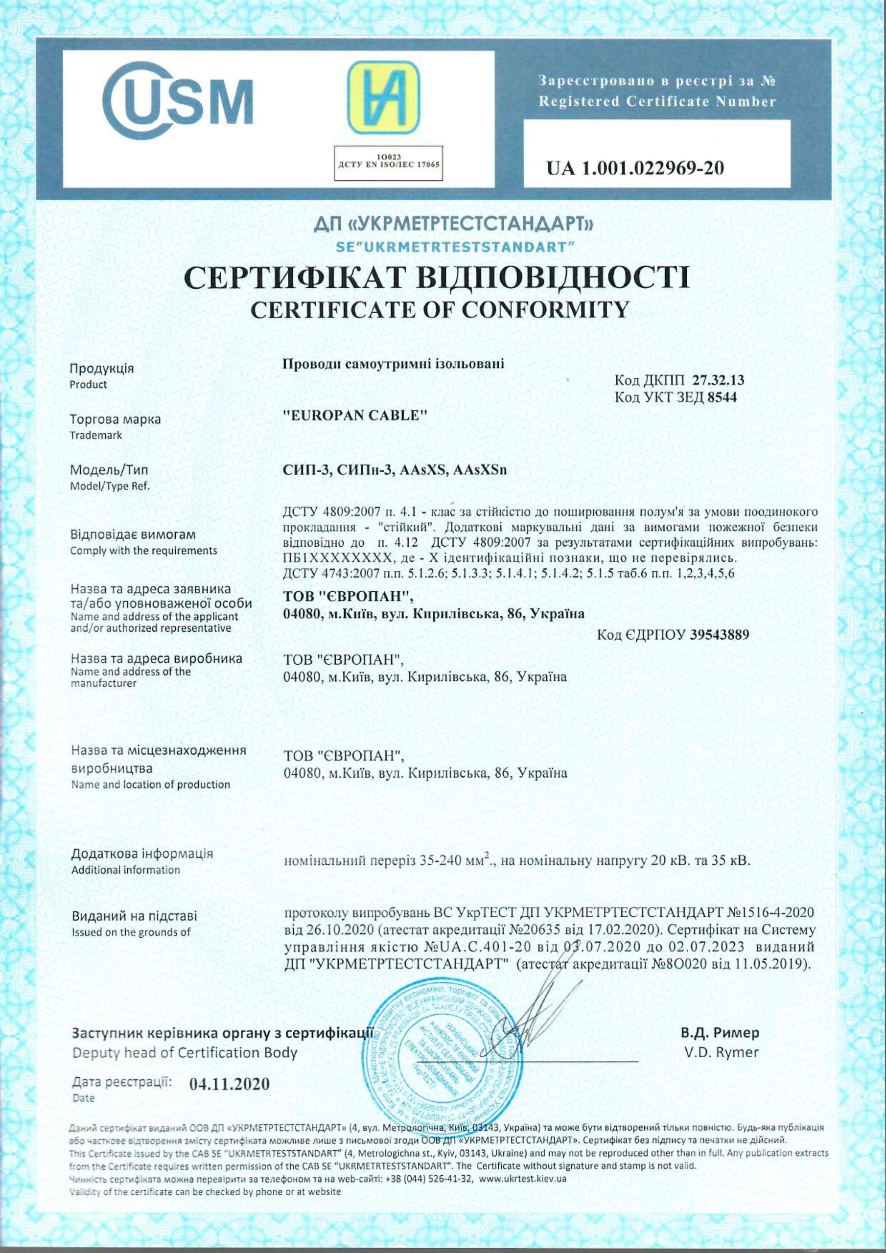
SIP-1, SIPn-1, SIP-2, SIPn-2, SIP-4, SIPn-4, SIP-5, SIP-5ng, AsXS, AsXSn
- SIP is a self-supporting insulated wire which is intended to transfer electrical energy in overhead power lines and branch off from trunk lines to enter into residential buildings and utility buildings. The laying is carried out on supports, as well as on the walls and structural elements of industrial and residential buildings.
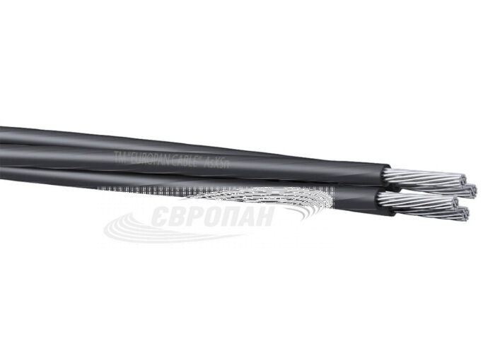
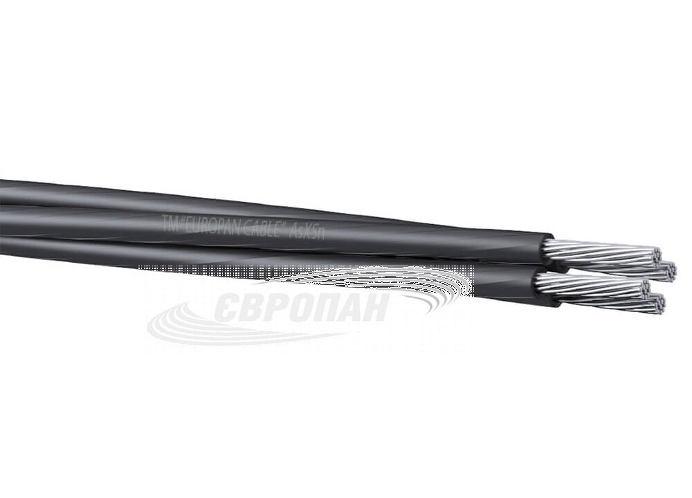
- AsXS is a self-supporting wire for overhead power lines with aluminum conductors, insulated with XLPE, resistant to ultraviolet.
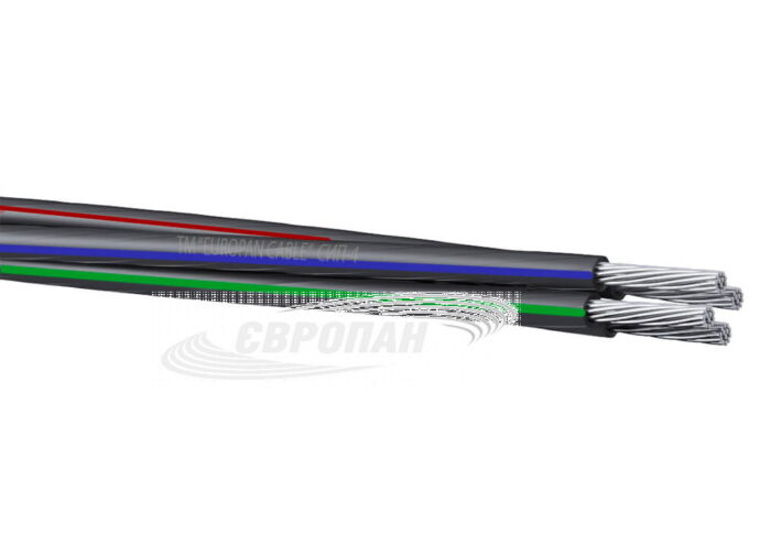
- AsXSn is a self-supporting wire with aluminum conductors, insulated with XLPE, resistant to ultraviolet, flame retardant.
- The wires are designed for the transmission and distribution of electrical energy in power and lighting networks for an alternating voltage 0.6/1 kV.
- The insulated wires with a neutral self-supporting conductor (SIP-1 and SIP-2) are intended for installation and reconstruction of overhead power transmission lines and linear branches from overhead lines, as well as descents to power electrical equipment.
- The insulated wires without a neutral self-supporting conductor (SIP-4, SIP-5 and AsXS, AsXSn) are intended for the branches from overhead power lines to the enter, and for the laying along the walls of buildings and structures.
operation: from -60°С to +50°С
S – self-supporting;
I – insulated;
P – wire;
n, ng – does not support combustion.
A – aluminum conductor;
s – self-supporting wire;
XS – insulation made of cross-linked polyethylene;
n – does not support combustion.
The number in the wire marking indicates the type of construction.
SIP-1 – with a non-insulated neutral self-supporting conductor;
SIP-2 – with an insulated neutral self-supporting conductor;
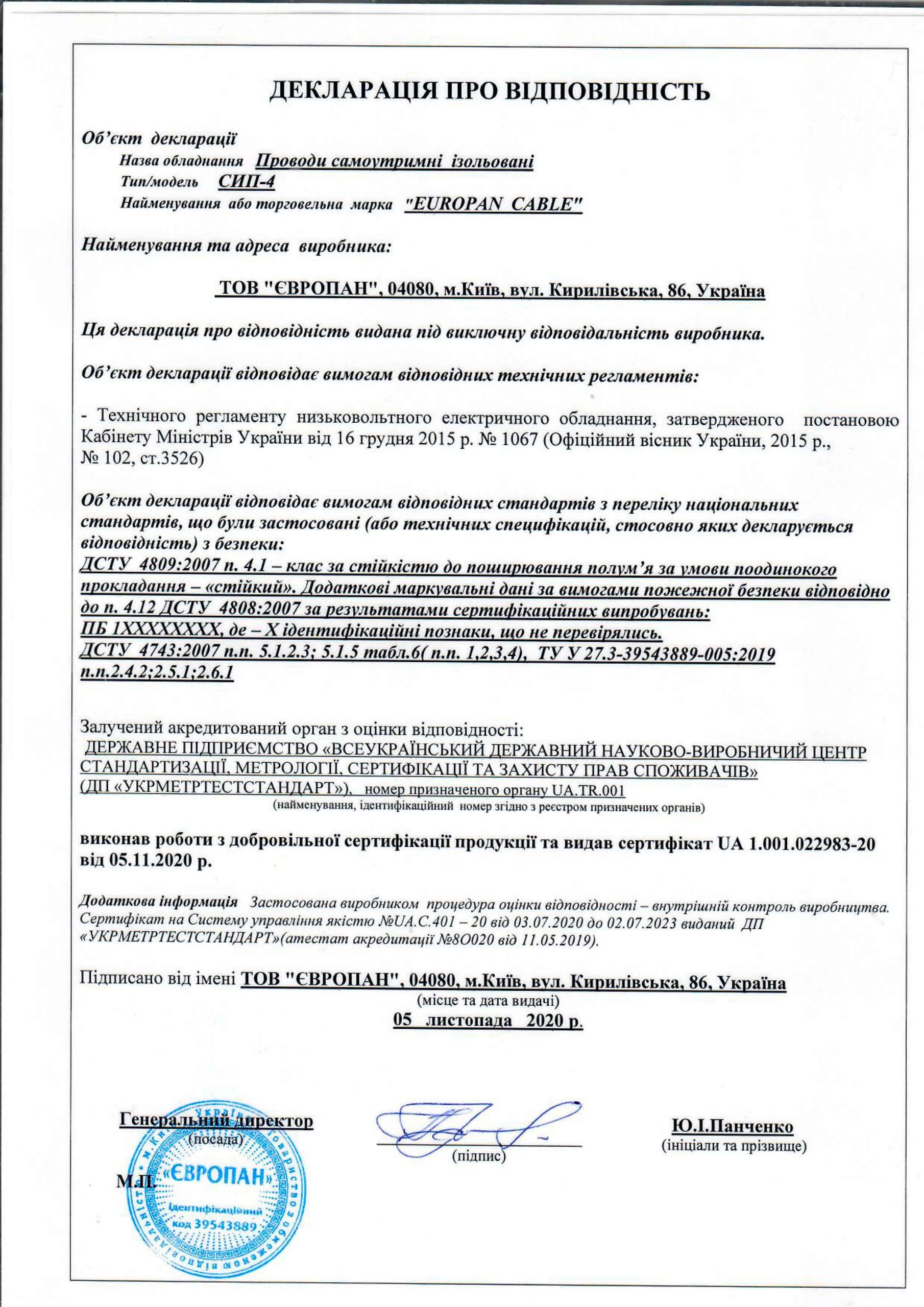
SIP-4 – without neutral self-supporting conductor with light-stabilized polyethylene insulation;
SIP-5 – without neutral self-supporting conductor, insulated with silanol-crosslinked light-stabilized polyethylene.
| Conductors: aluminum multi-wire (tables A.1, A.2 of the National Standards of Ukraine 4743:2007) |
| Insulation: light-stabilized polyethylene |
| Armor: no |
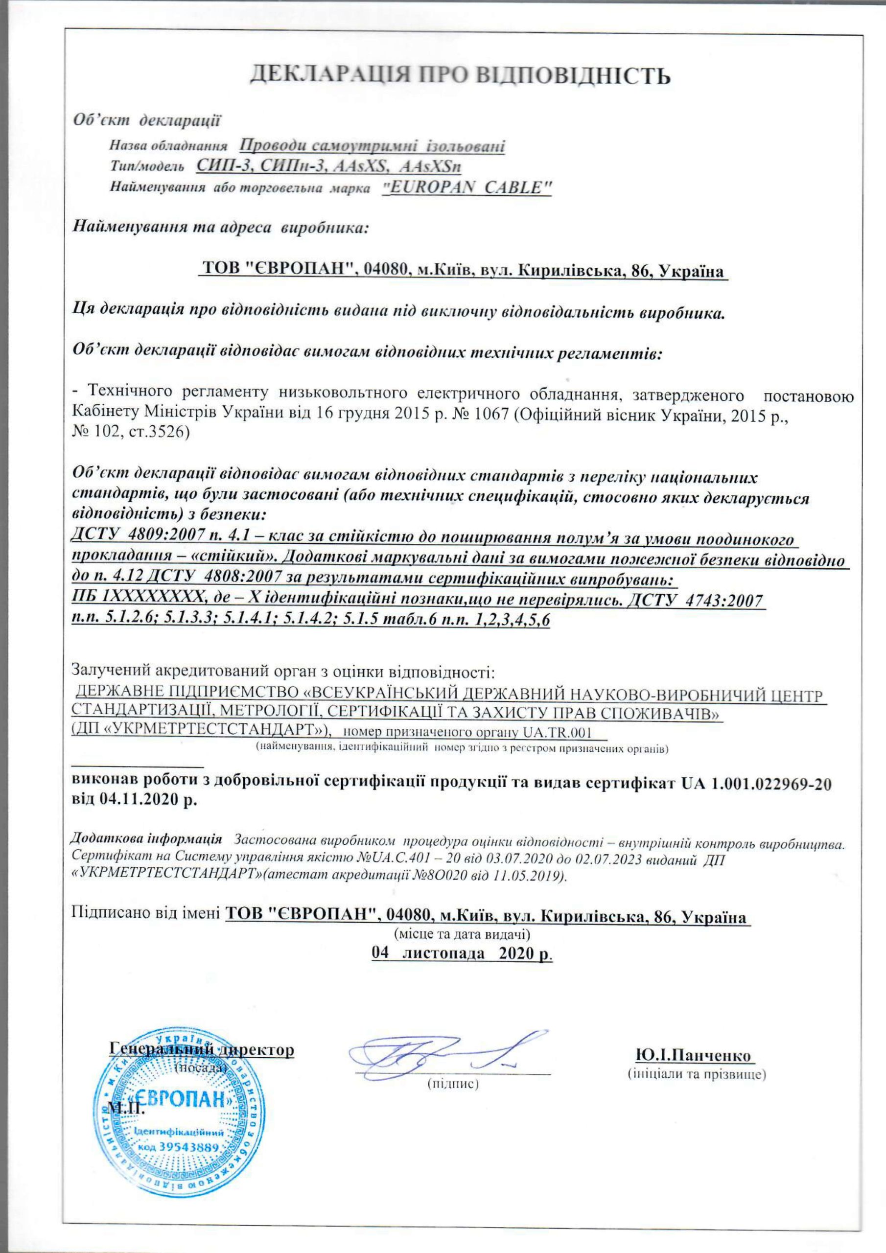
- The National Standards of Ukraine 4809:2007
- PB 1XXXXXXXX
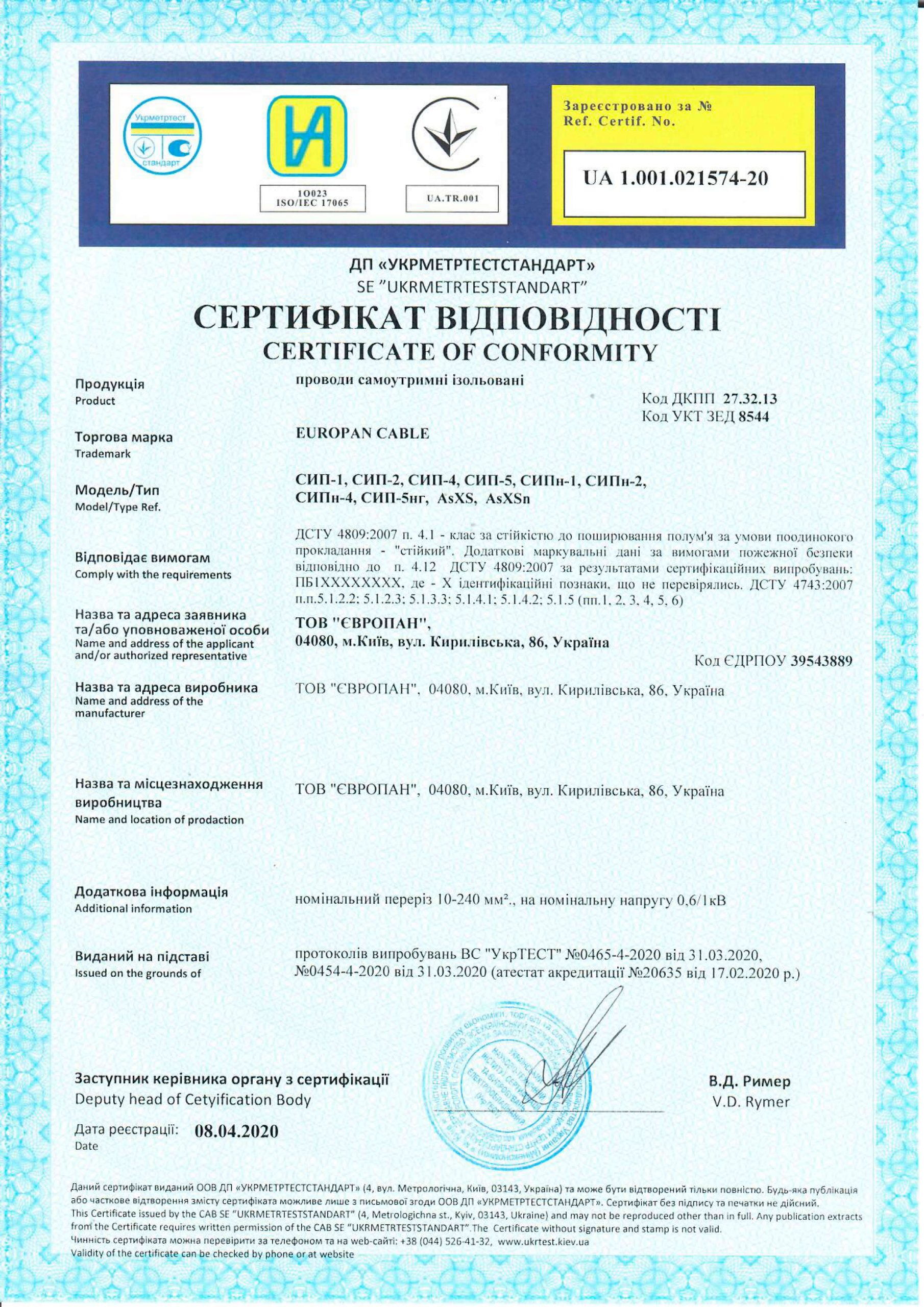

SIP, the self-supporting insulated wires, are used to transmit electrical energy in the overhead power and lighting networks at an alternating voltage of 0.6/1.0 kV with a frequency of 50 Hz. They are also used for branching from the trunk lines to the enter to residential buildings and utility buildings. The laying is carried out on supports, along the walls and structural elements of industrial and residential buildings.
SIP wires are easy to lay, they keep their shape well, do not sag under their own weight and do not require additional armouring. They are made from eco friendly materials and do not emit harmful substances into the surrounding nature.
Design of SIP
There are several types of SIP, they differ in design features and insulating material. A common feature is the insulation on the phase conductors. And the neutral carrier wire can be insulated, made without an insulating coating, or be absent at all.
The design of the wires is the aluminum insulated conductors of the same cross-section stranded into a bundle (tables A.1, A.2 of the National Standards of Ukraine 4743:2007). The conductors are always aluminum and never copper. The phase conductors can also be made of an aluminum alloy, and the neutral conductor consists of a steel core and an aluminum sheath. The electrical insulation of the conductors is made of cross-linked light-stabilized polyethylene or thermoplastic light-stabilized polyethylene.
In the regions with increased intensity of ultraviolet radiation, it is advisable to use wires with insulation of light-stabilized polyethylene, resistant to ultraviolet radiation and ozone. In places with a high probability of significant external heating of the wire during operation, use wires marked «n» and «ng», the insulation of which is made of non-combustible self-extinguishing materials. And in conditions of sudden temperature changes, adhesion of snow, icing and a similar environment, you should choose wires with thermoplastic insulation.
Types and applicability scope of SIP
SIP-1 is a wire in which all conductors, except for the neutral one, have an insulating coating. The neutral conductor is uninsulated, made of a steel core, and surrounded by aluminum wires. The phase aluminum conductors are covered with ultraviolet-resistant thermoplastic light-stabilized polyethylene insulation. All insulated conductors are stranded around neutral one.
In SIP-2, unlike the SIP of the first type, all conductors, including the neutral carrier conductor, are insulated. This is necessary to protect the neutral conductor in the areas with an aggressive environment (for example, in coastal areas) or places with a polluted climate (for example, near chemical plants). In SIP-2 wires, the neutral bearing conductor is also made of a steel core with the aluminum wires on the outside. And the insulation is made of thermoplastic light-stabilized polyethylene.
SIP-1 and SIP-2 are used mainly for the installation of overhead power lines, networks between cities and settlements, and for the branches to settlements.
In places with an increased likelihood of fire, it is customary to use flame-retardant wires SIPn-1 and SIPn-2.
SIP-4 is a wire with aluminum phase conductors, in which there is no bearing conductor, but all the wires are bearing. All conductors are of the same cross-section, insulated using thermoplastic light-stabilized polyethylene, resistant to ultraviolet radiation, temperature extremes and atmospheric precipitation. In the event of a short circuit and heating up to the melting temperature, the thermoplastic insulation «does not flow», but becomes viscous and, after cooling, regains its shape. Also, due to the design features, the SIP-4 wires are practically not susceptible to wet snow adhesion and ice formation. The insulation of the conductors must be marked in the form of longitudinal marks or stripes. At the same time, the digital marking is less common.
There is a type of wire with flame retardant insulation. Such a wire is marked with SIPn-4 and is used in conditions of increased fire hazard and for indoor installation.
SIP-4 is not used to build overhead lines, but is used only to branch off from them and supply electricity to dwellings and buildings for various purposes.
SIP-5 is similar to SIP-4, its design also lacks a neutral self-supporting conductor, and all phase conductors have an insulating coating of silanol-crosslinked light-stabilized polyethylene. It is the insulation material that is the main difference of this brand of wire. It has increased resistance to low temperatures and other destructive environmental influences. It has a higher melting point, which allows it to withstand higher heating temperatures and increased current loads. This wire distinguishes by increased tensile strength, elasticity and mechanical strength. It also restores shape after short-term deformation. The increased insulation strength increases the operating time at the maximum allowable temperature by 30%.
SIP-5 is used for installation on power line poles and for supplying street lighting to buildings. For laying inside buildings, inserting a wire to a switchboard or meter inside a house, as well as when laying in fire hazardous zones, for example, in forest belts and in dry and hot climates, use a non-combustible SIP-5 wire marked «ng».
According to their characteristics, wires of the AsXS and AsXSn brands are the European analog of SIP-5 and SIP-5ng.
Operation
The wires are designed for operation at the ambient temperatures from -60°C to +50°C. The laying without preheating is allowed at a temperature not lower than -20°C.
The bend radius during installation and the wire installed on the supports must be at least 10 outer diameters.
The permissible conductor heating temperature during normal operation is not more than +90°С. In the overload mode +130°С and during a short circuit +250°С.
EUROPAN Cable Plant produces high-quality insulated self-supporting wires using a modern production complex. You can select and buy our products from a warehouse or custom-built by filling out an application on the website or by calling the sales department. You can choose the required conductor on the website using the plant’s product catalog or with the help of our experts. Thanks to close cooperation of sales managers with employees of the technical department, we provide our customers with the most complete information on technical details and specific parameters, as well as the compliance of wires and cables with various international standards.
Permissible load current and permissible short-circuit currents of the wires
|
Nominal cross-section of the key conductors, mm2 |
Permissible load current, A, not more than |
Permissible current of one-second short-circuit of the wires, kA, not more than |
| 16 | 100 | 1,5 |
| 25 | 130 | 2,3 |
| 35 | 160 | 3,2 |
| 50 | 195 | 4,6 |
| 70 | 240 | 6,5 |
| 95 | 300 | 8,8 |
| 120 | 340 | 10,9 |
| 150 | 380 | 13,2 |
| 185 | 436 | 16,5 |
| 240 | 515 | 22,0 |
Select rated voltage, kV
|
Number of conductors and nominal cross-section, mm2 |
Nominal outer diameter, mm |
Weight of 1 km of wire, kg |
| 1 x 16 + 1 x 25 | 13,4 | 136 |
| 3 x 16 + 1 x 25 | 17,8 | 274 |
| 3 x 25 + 1 x 35 | 20,8 | 392 |
| 3 x 35 + 1 x 50 | 23,4 | 517 |
| 3 x 50 + 1 x 50 | 26,0 | 654 |
| 3 x 50 + 1 x 70 | 27,1 | 710 |
| 3 x 70 + 1 x 70 | 30,8 | 931 |
| 3 x 70 + 1 x 95 | 32,1 | 1002 |
| 3 x 95 + 1 x 70 | 33,7 | 1174 |
| 3 x 95 + 1 x 95 | 34,9 | 1246 |
| 3 x 120 + 1 x 95 | 38,2 | 1470 |
| 3 x 150 + 1 x 95 | 40,5 | 1697 |
| 3 x 185 + 1 x 95 | 45,0 | 2065 |
| 3 x 240 + 1 x 95 | 50,1 | 2521 |
Select rated voltage, kV
|
Number of conductors and nominal cross-section, mm2 |
Nominal outer diameter, mm |
Weight of 1 km of wire, kg |
| 3 x 16 + 1 x 25 | 20,6 | 306 |
| 3 x 25 + 1 x 35 | 21,8 | 428 |
| 3 x 25 + 1 x 54,6 | 23,2 | 489 |
| 3 x 35 + 1 x 50 | 24,6 | 566 |
| 3 x 35 + 1 x 54,6 | 25,0 | 581 |
| 3 x 50 + 1 x 50 | 27,1 | 703 |
| 3 x 50 + 1 x 54,6 | 27,7 | 718 |
| 3 x 50 + 1 x 70 | 28,6 | 777 |
| 3 x 70 + 1 x 54,6 | 32,1 | 939 |
| 3 x 70 + 1 x 70 | 32,1 | 997 |
| 3 x 70 + 1 x 95 | 33,5 | 1078 |
| 3 x 95 + 1 x 70 | 36,4 | 1241 |
| 3 x 95 + 1 x 95 | 36,4 | 1322 |
| 3 x 120 + 1 x 95 | 39,8 | 1546 |
| 3 x 150 + 1 x 95 | 43,8 | 1773 |
| 3 x 185 + 1 x 95 | 46,7 | 2141 |
| 3 x 240 + 1 x 95 | 50,1 | 2598 |
Select rated voltage, kV
|
Number of conductors and nominal cross-section, mm2 |
Nominal outer diameter, mm |
Weight of 1 km of wire, kg |
| 1 x 10 | 6,2 | 47 |
| 1 x 16 | 7,4 | 68 |
| 1 x 25 | 8,6 | 98 |
| 1 x 35 | 9,7 | 129 |
| 1 x 50 | 11,3 | 174 |
| 1 x 70 | 13,3 | 246 |
| 1 x 95 | 15,1 | 327 |
| 1 x 120 | 16,5 | 401 |
| 1 x 150 | 18,2 | 475 |
| 1 x 185 | 20,2 | 596 |
| 1 x 240 | 22,5 | 747 |
| 2 x 10 | 12,4 | 94 |
| 2 x 16 | 14,8 | 138 |
| 2 x 25 | 17,2 | 199 |
| 2 x 35 | 19,4 | 260 |
| 2 x 50 | 22,5 | 351 |
| 2 x 70 | 26,6 | 499 |
| 2 x 95 | 30,2 | 661 |
| 2 x 120 | 33,1 | 811 |
| 2 x 150 | 36,3 | 962 |
| 2 x 185 | 40,4 | 1207 |
| 2 x 240 | 44,9 | 1512 |
| 3 x 10 | 13,4 | 142 |
| 3 x 16 | 15,9 | 207 |
| 3 x 25 | 18,5 | 298 |
| 3 x 35 | 20,8 | 391 |
| 3 x 50 | 24,2 | 527 |
| 3 x 70 | 28,6 | 748 |
| 3 x 95 | 32,4 | 991 |
| 3 x 120 | 35,5 | 1216 |
| 3 x 150 | 39,0 | 1443 |
| 3 x 185 | 43,4 | 1811 |
| 3 x 240 | 48,3 | 2267 |
| 4 x 10 | 15,0 | 189 |
| 4 x 16 | 17,8 | 276 |
| 4 x 25 | 20,8 | 397 |
| 4 x 35 | 23,4 | 521 |
| 4 x 50 | 27,1 | 703 |
| 4 x 70 | 32,1 | 997 |
| 4 x 95 | 36,4 | 1322 |
| 4 x 120 | 39,8 | 1621 |
| 4 x 150 | 43,8 | 1924 |
| 4 x 185 | 48,7 | 2415 |
| 4 x 240 | 54,2 | 3023 |