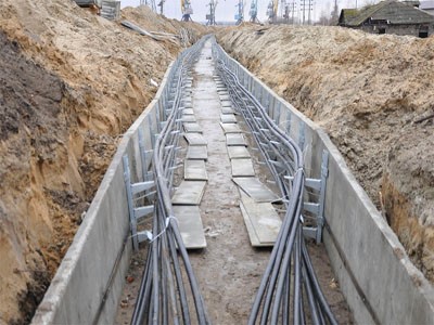
Channel wiring
A cable channel is an extended closed non-passable structure, fully or partially buried in the ground, covering or floor, which allows laying cable lines, carrying out their repairs and inspections after removing the covering without carrying out earthworks.
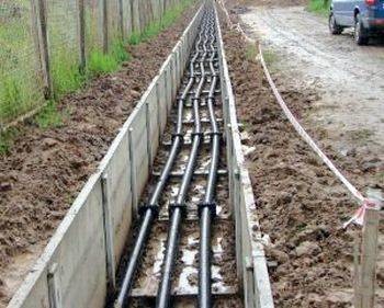
Laying in the cable channel provides a high protection of cable lines from mechanical damage and is used both outside and inside industrial premises.
The placement of cable channels is not allowed in areas where may be spilled the molten metal, high temperature liquids or substances that have a destructive effect on cable sheaths.
Channels are constructed from unified prefabricated reinforced concrete structures and, less often, from monolithic reinforced concrete or bricks. There are trough-type channels with ceilings (photo a) and channels made of prefabricated wall slabs with bases and ceilings (photo b).
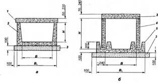
There are channels of various widths and heights, rectangular or square cross-section. The depth of the channel should be no more than 1.2 m. And the width – at least 0.3 m for the channels up to 0.6 m deep, at least 0.45 m – for the channels with a depth of 0.6 m to 0.9 m, and not less than 0.6 m – for the channels with a depth of 0.9 m to 1.2 m.
On their top the channels have removable plates and they are protected with waterproofing. If the channels are located outdoors in unprotected areas, then they are made underground with the layer of ground as a covering with a thickness of at least 0.3 m on top of removable plates. In the case of intersection with motor roads, the channels are deepened by 0.7 m, and with railways – by 1 m. To prevent oil, ground, storm and process waters from entering the channels, their bottom is made at a slope of at least 0.5% towards the water collectors or storm sewers.
In cable channels built outdoors and located above the groundwater level, it is allowed to use an earthen bottom with drainage (filling with compacted gravel or sand 10-15 cm thick). And channels located in wet soils or below the groundwater level are made with waterproofing of the bottom and walls.
It is not necessary to cover cable channels with ground on the top of removable plates in fenced areas, accessible only to service personnel.
If the channels are located inside the premises, they are covered with removable plates made of non-combustible materials at floor level.
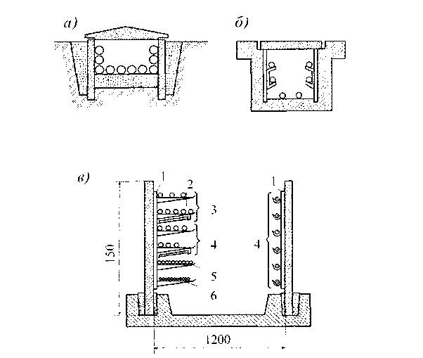
- a) external channel, b) internal channel,
In electrical machinery and similar rooms, the channels are covered with corrugated steel, and in control rooms with parquet or synthetic flooring, they are covered with wooden shields protected from below by plates of non-combustible material.
At the entry points of the channels into the buildings, they are separated from the structures by fireproof partitions.
Cable channels must be made taking into account the possibility of additional cable laying in them in an amount of at least 15% of the number provided for by the project.
The cables with flame retardant sheaths will be used for laying in channels.
Cables are laid in channels along the bottom or on supporting structures installed on its walls. Laying along the bottom of the channel is used if its depth does not exceed 0.9 m. The distance between the group of power cables above 1 kV and the group of control cables must be at least 0.1 m or these groups of cables must be separated by a partition made of non-combustible materials.
For laying cables along the channel walls, cable racks with shelves or profiles with embedded suspensions are used. The arrangement of the cables can be performed:
– on one channel wall on hangers or shelves;
– on both walls on hangers or shelves;
– on one wall of the channel on hangers, on the other wall – on shelves
The location of the cables and their fastening to the structures is selected depending on their voltage, section and type.
According to the rules for electrical equipment installation, cables should be placed in cable structures in the following sequence:
- a) with a double-sided arrangement of cable structures, control cables should be placed, if possible, on the opposite side from the power cables. With a one-sided arrangement of structures, control cables and communication cables are located only under or above power cables, separating them with a partition;
- b) control cables are allowed to be laid next to power cables with voltage up to 1 kV;
- c) power cables with voltages up to 1 kV are laid mainly over cables with voltages above 1 kV, separating them with a partition;
- d) different groups of cables: working and reserve cables with voltage above 1 kV from generators, transformers and cable lines supplying power consumers of category I, should be laid mainly at various horizontal levels and separated by partitions. In the case of double-sided placement of cable structures, cables supplying power consumers of category I should be laid on consoles on opposite sides.
In case of automatic fire extinguishing using air-mechanical foam or sprayed water, the partitions specified in subparagraphs a), c) and d) may not be installed.
Couplings on power cables are laid on a separate shelf of the supporting structures and enclosed in a protective fire casing, which must be separated from the upper and lower cables along the entire width of the shelves by protective barriers. Each tunnel and channel must provide free rows of shelves for laying couplings.
For the passage of cables through partitions, walls and ceilings, bushing sleeve made of non-combustible pipes must be installed. In places where cables pass through pipes, the gaps in them must be carefully sealed with non-combustible material. The filling material should provide adhesion and be easy to break if additional cables are laid or if they are partially replaced.
The number of cables in the channel can be different and depends on their diameter and the brand of the typical channel. Channels with maximum sizes can accommodate up to 60 power cables. If it is necessary to lay a large number of cables, double (three-walled) channels are used, which, however, complicates the implementation of branches to individual consumers.
With a short channel length (50 – 100 m), the cable is rolled out by hand. With long channels, the cable is laid in a mechanized way, using winches and rolling rollers, as is done when laying in trenches.
The main advantage of laying cables in channels is their reliable protection from mechanical damage. In addition, this method of laying makes it possible to inspect and repair cable lines during operation, to lay a new or replace an existing cable without excavation.
The disadvantages of laying in the channels include difficult air exchange and heat removal due to the limited size of the channel; overcrowding of cables and, as a result, the possibility of their mutual damage in the event of an arc; as well as the need to open the upper channel cover during inspection or repair of cables.


